


Description
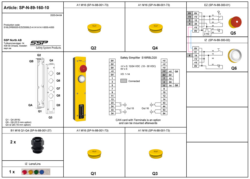
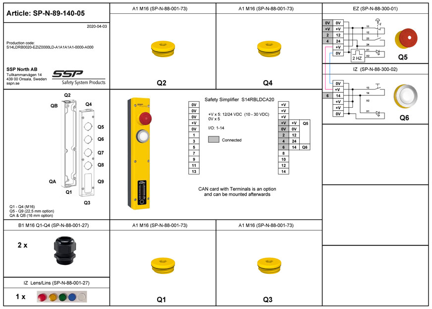
Safety Simplifier PLC with prewired E-stop and one Push Button. The E-stop has automatic flashing when pushed.
A safety PLC with prewired E-stop and a Push Button for optional use. It comes with 5 different colour caps witch gives you the free option. The cap is easily clicked on the Push Button. This model is intended for a safety solution for a single machine or for a combination of several machines and safety devices. This unit has free safety I/O for safety devices and for machines which make it easy design a safety system which fulfill the safety requirements.
Read moreSafety Simplifier PLC with prewired E-stop and one Push Button. The E-stop has automatic flashing when pushed.
A safety PLC with prewired E-stop and a Push Button for optional use. It comes with 5 different colour caps witch gives you the free option. The cap is easily clicked on the Push Button. This model is intended for a safety solution for a single machine or for a combination of several machines and safety devices. This unit has free safety I/O for safety devices and for machines which make it easy design a safety system which fulfill the safety requirements.
-In our free software Simplifier Manager you can select function blocks for E-stop, Push Buttons, safety devices and outputs for your machines.
-The I/O:s can be selected in the Software Simplifier Manager as Inputs, Outputs or as a combination of input and output at the same time.
-Connected I/O to cables and M12 contacts can be selected in the software as inputs, outputs or a combination for safety devices and machines.
-An I/O can also be set as a fixed voltage output, same as power supply, in the software.
-The flexibility of the I/O allows different function for the same connection to a cable. The same cable can then be used for different sensors as the function is selected in the Simplifier Manager.
Example of Safety Devices which can be connected to the I/O:s and be programmed in Simplifier Manager:
- Door sensors
- Door locking
- Light curtains
- Safety edges and Safety mats
- Two hand devices
- Bypassing combinations
- Laser Scanners
- Enabling and hold to run devices
- Interlocked doors and hatches
- Position control
- Reset Push Buttons with indication
- Start and stop Push Buttons
- E-stops
All I/O can be set as:
– OSSD outputs with short circuit detection
– safety outputs to machines
– pulse coded outputs for short circuit detection
– fixed voltage output
Double relay outputs are commonly used for E-stop and Safety stop for
- Industrial robots
- Other machinery which need to differ between different stops
- Machines which need to have potential free contacts
Internal function selections
USB-contact is standard on all units
Wireless programming, on-line and bus communication on 2,4 GHz
Relay outputs on output 15 and 16: 2 x NO which can be used in parallel or in serie
See also electrical drawing.
CAN-card: Terminals for optical isolated connection to CAN bus. The power supply to the CAN-card only need to be connected in one of the Safety Simplifiers. The supply from one is enough for all CAN-cards witch are connected to each other. See also electrical drawing for CAN
Options:
ID/Log memory card: Select this card if you want to be able to exchange a unit and program the new unit with the card. On this card the software for the unit will be stored as well as logged information (both standard and selectable information). This card always has to be inside a Safety Simplifier as the card has the ID of the unit.
Log card: This card is used to log information on the card (standard information and selected information by the one who programs). The ID of the Safety Simplifier is the unique code inside a Safety Simplifier. For exchange you need to put in the new number from a new Safety Simplifier.
No card: The ID of the Safety Simplifier is the unique code inside a Safety Simplifier. For exchange you need to put in the new number from a new Safety Simplifier.
Models
Art. No. SP-N-89-160-08 + ID/Log m. card
Art. No. SP-N-89-160-08 + Log card
Art. No. SP-N-89-160-08
Art. No. SP-N-89-160-10 + ID/Log m. card
Art. No. SP-N-89-160-10 + Log card
Art. No. SP-N-89-160-10
Art. No. SP-N-89-140-04 + ID/Log m. card
Art. No. SP-N-89-140-04 + Log card
Art. No. SP-N-89-140-04
Art. No. SP-N-89-140-05 + ID/Log m. card
Art. No. SP-N-89-140-05 + Log card
Art. No. SP-N-89-140-05


